- Projekt:
- https://wiki.muc.ccc.de/geigercounter:start
- Name:
- PiGi Geigercounter
- Beschreibung:
-
Sammelbestellung: Board & Bauteile für PiGi
- Lizenz:
- --
- Beteiligt:
- 9R,
- Status:
- läuft
- Kategorie:
- Hardware, Software
- Verwandtes:
- Labor
Geigercounter
Eckdaten
Preis für Board & einen einzeln teuer zu beschaffenden Poti: ~1,70€
weitere Kosten
~10€ für benötigte Bauteile
>10€ für eine GeigerMüllerZählrohr
Mit ~30€ einsatz sollte sich damit also ein einfacher Geigerzähler bauen
lassen.
Arbeitsaufwand:
anfängerfreundliches SMD-Löten
Was kann das Ding:
Das Board erzeugt die zum Betrieb des GMZ nötige Hochspannung & gibt bei
detektierter Strahlung eine falling edge aus die von RasPi, Arduino,
ESP* oder sonstwas weiterverarbeitet werden kann.
Details auf der Projektseite
kit
bag content
| pc | item | content |
|---|---|---|
| 1 | GM-tube type SBM-20 | http://www.gstube.com/data/2398/ |
| 1 | board | - |
| 1 | green bag | C1-4, T1-3, IC1, L1 |
| 1 | clear bag | R1-9, J1 |
build
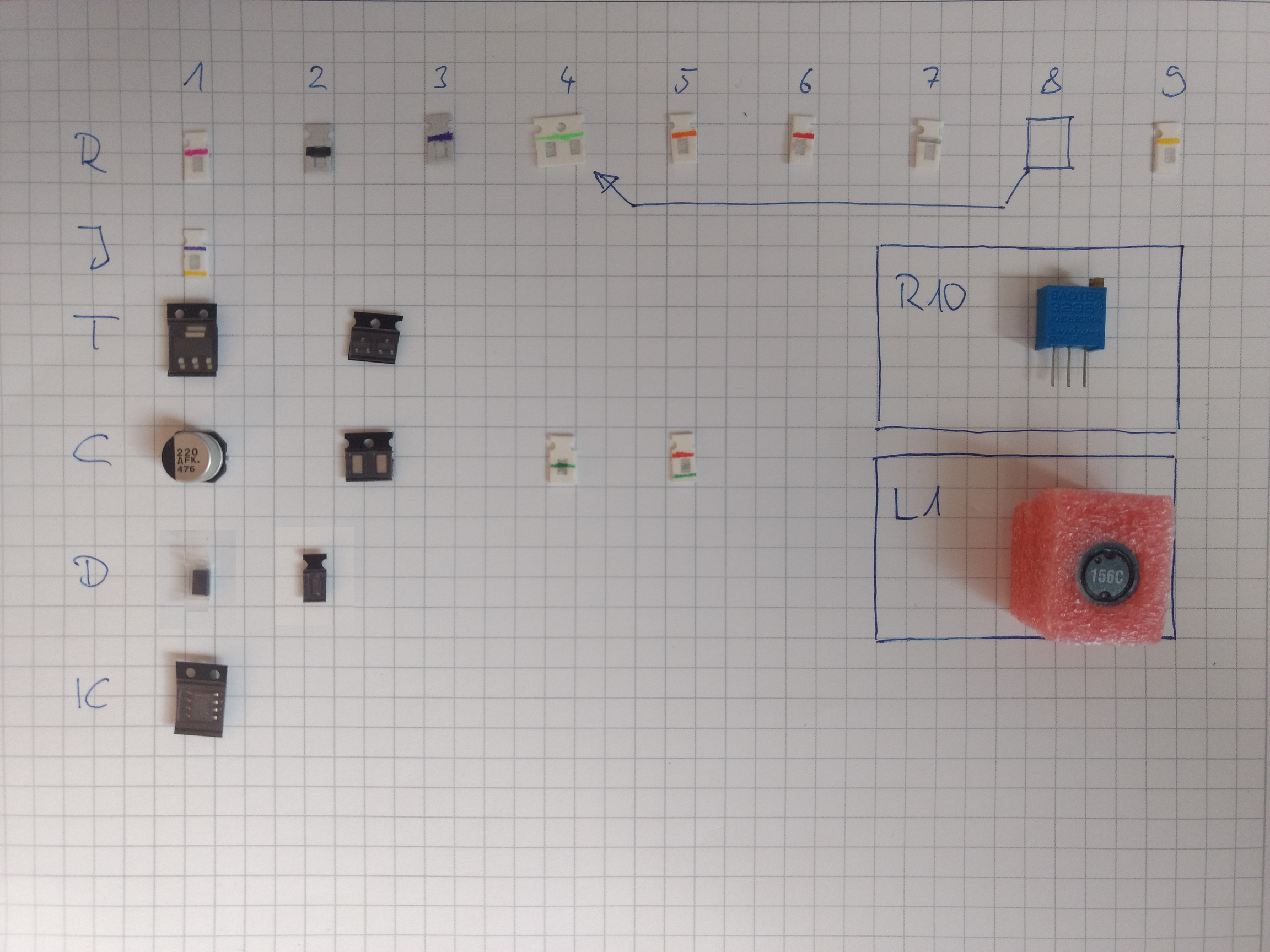
Below is a list of all parts with their marking and recommended solder order.
 Before you start building it, please make sure
- no parts are missing (compare content of bags in your kit to the list above)
- you have read and understood the documentation
- especially the hardware section
bottom
part
| # | V1.1 | Part/Value | Package | Marking | Notes |
|---|---|---|---|---|---|
| 1 | D2 | MMSD4148 | black belt | mark facing towards C4 | |
| 2 | C4 | 1nF | 0805 | green | |
| 3 | R5 | 330 ohms | 0805 | orange | |
| 4 | R4 | 100k | 0805 | light green | |
| 5 | R6 | 220k | 0805 | red | don't confuse with R1 |
| 6 | R1 | 1k | 0805 | pink | don't confuse with R6 |
| 7 | R9 | 27k | 0805 | yellow | |
| 8 | IC1 | TLC555QDRQ1/ICM7555 | SOIC-8 | 8 pins | Case mark facing towards R6 |
| 9 | T2 | MMBT4401 | SOT-23 | black package , 3 pins | |
| 10 | J1 | 0 Ohm | 0805 | yellow/violett | can be solder bridged instead of placing part |
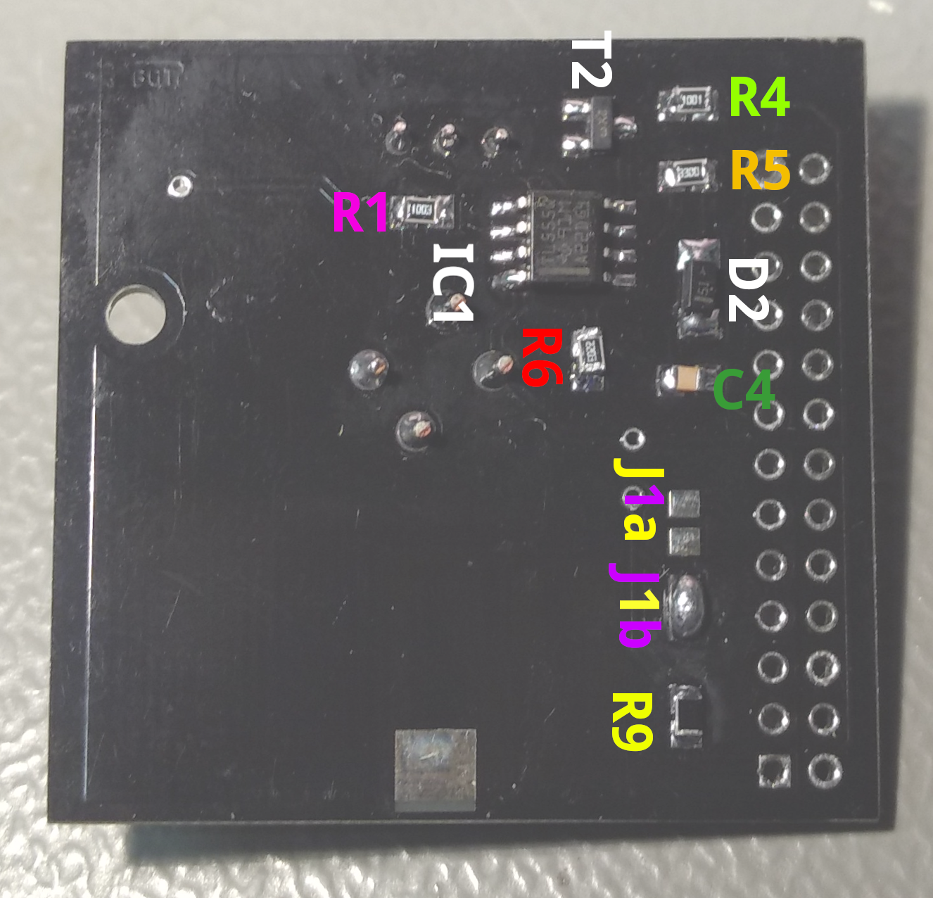
In the picture above the J1b is closed. This routes the output signal to Pin 7 (GPIO4) on the RaspberryPi. Alternatively, you can close J1a, which would output the signal to Pin 11 (GPIO17)
top
| # | V1.1 | Part/Value | Package | Marking | Notes | |
|---|---|---|---|---|---|---|
| 1 | C5 | 330pF | 0805 | red/green | ||
| 2 | R7 | 1.5k | 0805 | grey | ||
| 3 | R8 | 100k | 0805 | light green | default - see signals for alternative values | |
| 4 | T3 | MMBT4401 | SOT-23 | black package, 3 pins | ||
| 5 | C1 | 220uF/10V LowESR Aluminium Electrolytic Capacitor | see BRD | loose | black mark towards open hardware logo (=rounded corners towards T3) | |
| 6 | C2 | Vishay MLCC 10nF/1kV | 1206 | black package, 2 lightbrown parts | ||
| 7 | C3 | Vishay MLCC 10nF/1kV | 1206 | black package, 2 lightbrown parts | ||
| 8 | R2 | KOA Thick Film 1M 0.25W 0.5% | 1206 | black | ||
| 9 | R3 | KOA Thick Film 4.7M 0.25W 1% | 1206 | violet | ||
| 10 | D1 | Vishay BYGM23 Fast Recovery Diode 1.5A/ 1000V/ 75ns | DO-214AC (SMA) | clear package | mark towards R2 | |
| 11 | T1 | STN0214 Bipolar NPN 1k2V | SOT-223 | black package | ||
| 12 | L1 | Murata Shielded Inductor 15mH | see BRD | pink foam, 4 pins | algin dot mark with dimple (above “1”) | |
| 13 | R10 | Bourns Trimmer 100R | see BRD | blue trimmer | screw towards T1 | |
| * | — | R10a | optional, with a fixed value instead of R10 | 0805 | - | |
| 14 | H1 | Stacking Raspberry Pi Header | 2×13 2.54mm | - | optional - not included in the kit | |
